Av Araguaney QTA El Refran
Lecheria-Anzoategui, Venezuela
J-503572507
Lunes a Viernes: 8AM - 7PM
Fin de semana: 8AM - 12PM
TWERD ENERGO-PLUS Drives for Artificial Lift Solutions in Oil & Gas and industry in general.
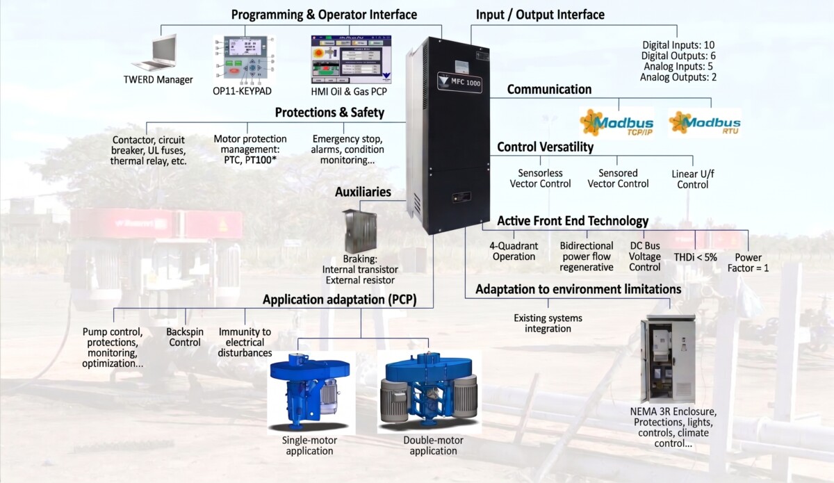
Regenerative Active Front End (AFE) technology, which involves replacing the traditional uncontrolled diode-based rectifier with a fully controlled rectifier based on state-of-the-art IGBTs; these are managed via vector control algorithms that enable precise control of power flow while ensuring robust motor operation in the face of grid disturbances.
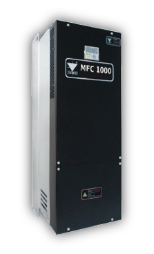
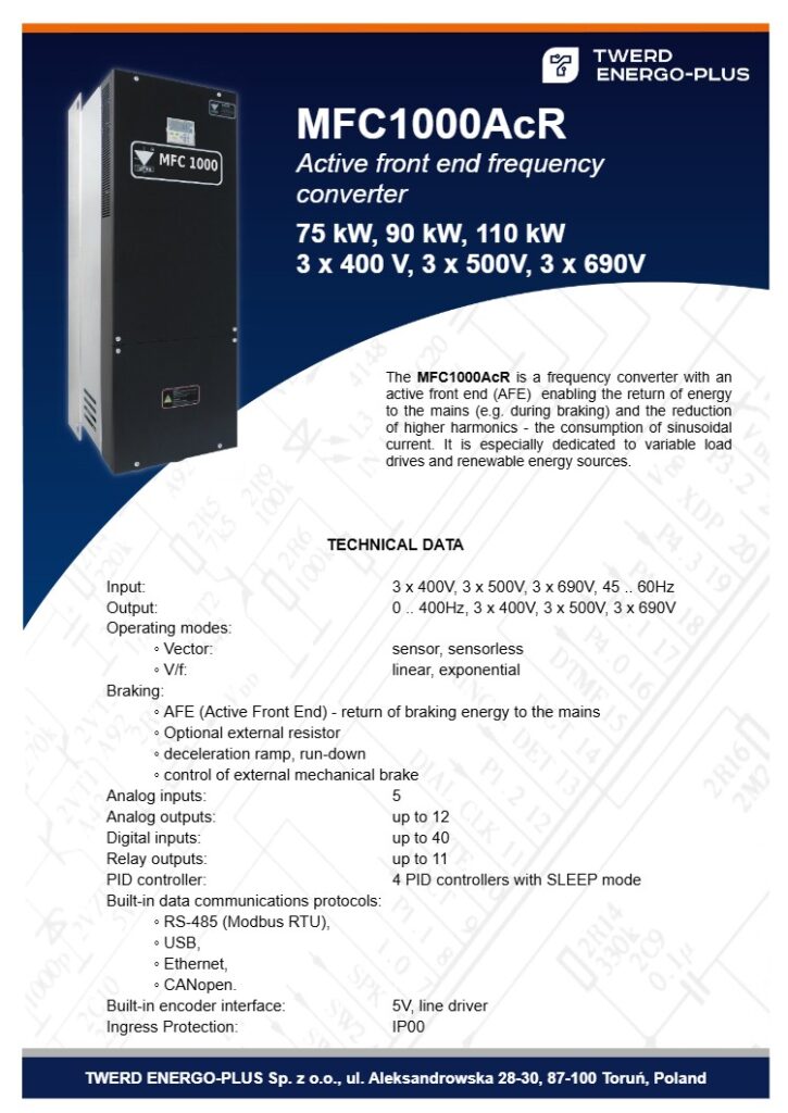
The MFC1000AcR is an active-input frequency converter. This technology enables energy feedback to the grid (e.g., during braking) and further harmonic reduction (sinusoidal current consumption). It is specially designed for variable-load drives and renewable energy sources.
Power supply: 3 x 500 V or 3 x 690 V, 45–60 Hz
Outputs: 0–400 Hz, 3 x 400 V, 3 x 500 V, or 3 x 690 V
Output current:
Overload: 1.5 In for 60 seconds every 10 minutes
Operating modes:
Vector DTC-SVM: sensorless and with rotor position sensor.
Scalar V/f: linear, exponential. Built-in 4 PID controllers with “SLEEP” function
Built-in incremental encoder interface (5V line driver)
Braking types:
AFE: regenerated energy can be fed back to the power supply;
Braking resistors (special cases)
Based on specified speed ramp or coast-to-stop;
External mechanical brake control.
Analog inputs: 5
Analog outputs: 2 (up to 12 with expansion module)
Digital inputs: 10 (up to 40 with expansion module)
Relay outputs: 6 (up to 11 with expansion module)
Built-in communication interfaces:
RS-485 (Modbus RTU);
USB;
Ethernet;
CANopen.
IP rating: IP21
External dimensions: 300x900x430 mm
Weight: From 100 kg – depending on the model
| AFE TECHNOLOGY | RECTIFIER DIODE TECHNOLOGY | |
|---|---|---|
| Regeneration | ||
| THDi | less than 5% | 70–80% (without using a filter) |
| DC bus voltage control. | ||
| Dynamic braking control without the use of braking resistors. | ||
| Voltage drop compensation for long cable runs between VFD and motor | ||
| Immunity of the output voltage against mains voltage dips or fluctuations. | ||
| Power factor | 1 | 0.70 - 0.95 |
The MFC1000/AcR variable speed drive features Active Front End (AFE) technology, delivering excellent performance in reducing harmonics fed back into the grid, maintaining a unity power factor, and enabling four-quadrant operation.
It utilizes vector-controlled torque technology to meet demanding requirements for high starting torque, speed precision, and torque control.
Suitable for a wide range of applications, it offers PID control, a user-friendly interface, flexible I/O expansion, fieldbus communication modules, comprehensive protection, adaptability to harsh environmental conditions, and easy maintenance.
It features BCP software specifically designed to meet the mechanical and electrical requirements of the oil industry, ensuring greater reliability by reducing deferred production barrels associated with momentary power interruptions.
Prompt production recovery via backspin control and automatic restart functions.
Production optimization and reduced energy consumption.
Substantial improvement in power quality: Low-harmonic equipment with unity power factor that does not introduce grid pollution, ensuring optimal utilization of the electrical system.
Integrated protection for the pumping unit, ensuring operational optimization.
Avoid production losses caused by power supply interruptions by maintaining well operations.
Minimizes downtime and allows production to resume without on-site operator intervention.
Prevents mechanical damage to the pump unit.
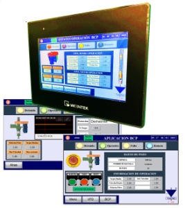
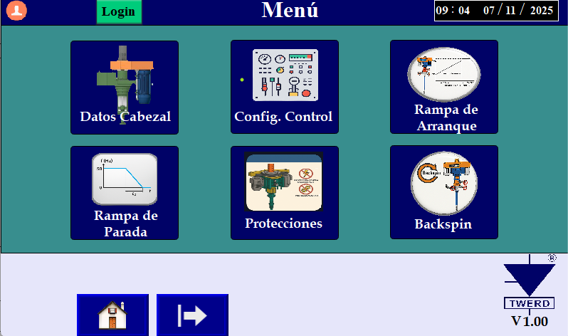
A touchscreen interface featuring dedicated software designed to deliver superior reliability and control for Progressive Cavity Pump (PCP) artificial lift systems, with the capability to operate without external downhole, surface, or pump sensor connections. It is a complete, integrated solution that eliminates the need for external PLCs.
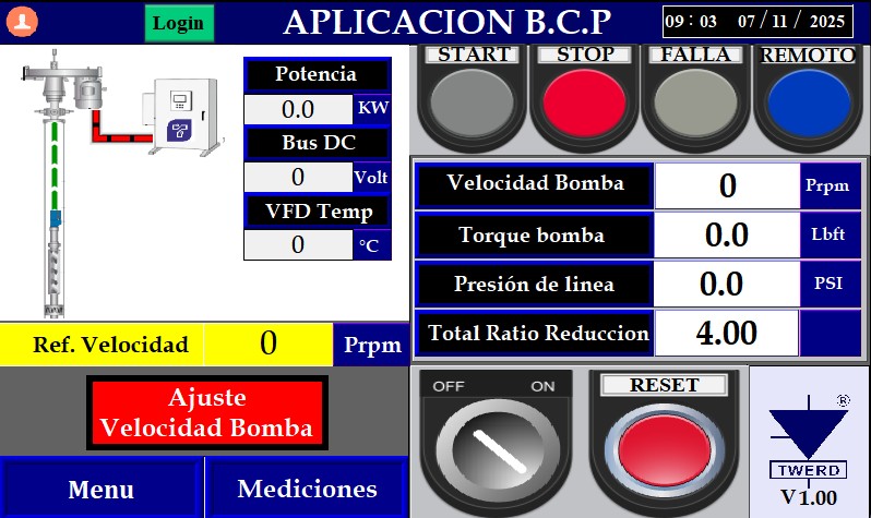
This oilfield HMI, specifically designed for PCP systems, is a key tool that enables quick and user-friendly configuration of the TWERD variable speed drive. Its interface speaks the language of the field operator, ensuring more precise VFD programming. Furthermore, it allows for a rapid response to potential faults, thereby reducing downtime and optimizing production.
Display: 7″ TFT (optional up to 10″)
Resolution: 800 x 480
Dimensions: WxHxD 200.3 x 146.3 x 35.0 mm
Mount: Panel mount
Memory:
Flash 4 GB
RAM 1 GB
Processor: Quad-core RISC
USB Host: USB 2.0 x 1
Ethernet Port:
LAN 1: 10/100 Base-T x 1
LAN 2: 10/100 Base-T x 1
COM Port:
Con.A: COM2 RS-485 2W/4W, COM3 RS-485 2W
Con.B: COM1 RS-232 4W, COM3 RS-232 2W*(1)
Power Supply: 24±20% VDC
Power Consumption: 820mA @ 24VDC
Protection Structure: UL Type 4X (indoor use only) / NEMA4 / IP66 Compliant Front Panel
Operating Temperature: 0° ~ 55°C (32° ~ 131°F)
Software and Features
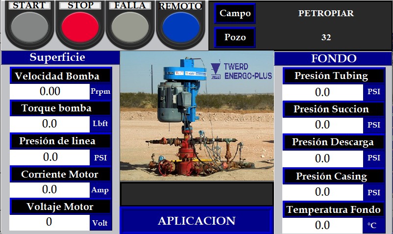
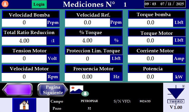
Measurement of VFD parameters during operation and display of key process variables.
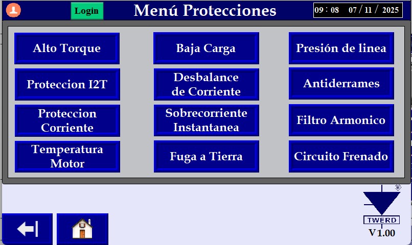
Protection configuration: (High torque, low torque, motor protections, speed limits, locked rotor, among others).
Configuration of downhole pressure measurements and alarms (High and low pressure).
Backspin control configuration.
Motor data and wellhead ratio configuration.
Configuration of two possible pump control modes (speed control or PID downhole pressure).
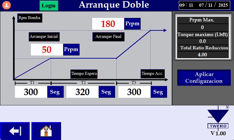
Micro-outage management configuration (automatic restarts and rapid recovery ramps).
VFD local/remote operation configuration.
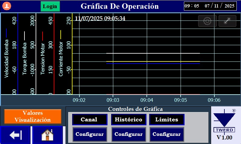
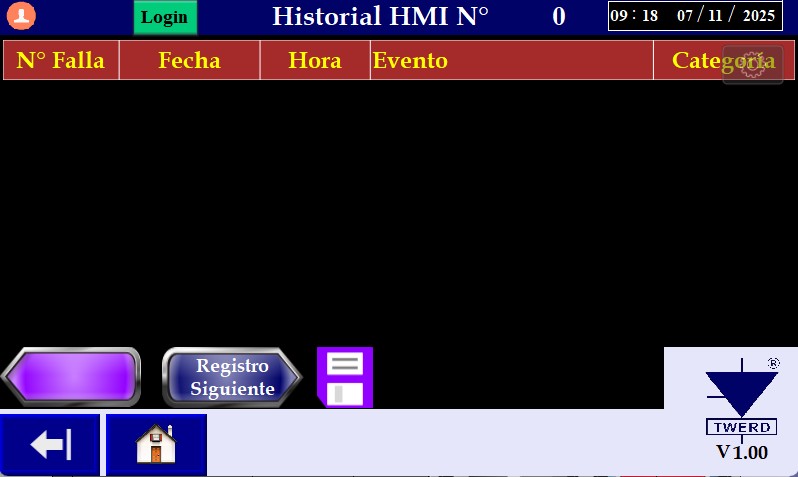
Fault log history with date and time (Downloadable to USB memory). Real-time and historical trend graphs for up to 6 variables, plus a multi-channel view capable of displaying 4 signals simultaneously in real time.
Datalogger function for a comprehensive record of process variable behavior over up to 90 days (downloadable to USB drive).
Option to remotely monitor and control the VFD via a mobile app (optional).
This HMI not only simplifies drive setup and operation but also enhances safety, reduces downtime, and increases production efficiency in oilfield applications using PCP pumps.
Input | Power | 150 HP |
Voltage | 3-phase AC 380V-480V (-15%-+10%) | |
Input frequency | 60 Hz ±5% | |
Rectifier technology | IGBT Active Front End | |
Rectifier switching frequency | 2.5 kHz | |
DPF displacement factor = Cos phi | cos1 (fundamental) | |
Electrical micro-cuts | 500ms | |
Current THD | <5% | |
Input Filter | Built-in LCL | |
Quadrants | Yes (4-quadrant operation) | |
Output | Output Frequency | 0,0...400 Hz U/f operation mode 0,0120 Hz - Vector operation mode |
Output Current | 180 A | |
Output Voltage | 0 a Un | |
Efficiency | 98% at rated load | |
Control System | Control Method | Linear, Quadratic U/f Scalar Sensorless DTC-SVM Vector-based DTC-SVM with rotor position sensor |
Switching frequency | 1 a 8 kHz | |
Modulator | SVPWM | |
Speed reference type | Analog Inputs Control Panel Potentiometer PID controller RS232 or RS485 communication bus Other possibilities. | |
Overload capacity | Instantaneous overload torque 0–60 Hz, 60 seconds | 150% |
Starting Torque (Between 0 and 0.5 Hz) 3 seconds | 200% | |
Environmental conditions | Operating ambient temperature | -10°C a +50°C |
Ambient storage temperature | -25 Ca +55°C | |
Humidity | 5% a 95% | |
Altitude | 1,000 m.a.s.l. | |
Protections | Motor Protection | Stall motor Motor Overload (thermal model) Output current limiting Current imbalance Voltage imbalance Motor overtemperature (PT100, PTC) Speed Limit Torque Limitation Speed discrepancy Ground fault |
Drive Protections | IGBT Overload Phase loss Low input voltage High input voltage High-voltage DC bus voltage limit, Low-voltage DC bus IGBT temperature LCL filter over-temperature Power supply failure Ground fault Loss of analog input signal Loss of speed reference Emergency stop | |
Hardware | Digital inputs | 10 digital inputs DI1...DI10 Digital Outputs 0/(15...24)V, Rin ≥ 3k Ω. The possibility of obtaining up to 30 digital inputs on expansion cards. |
Digital Outputs | 6 salidas digitales a relé K1... K6 - breaking capacity: 250V/1A AC, 24V/1A DC. . The possibility of obtaining up to 11 digital outputs on expansion cards. | |
Analog Inputs | 5 entradas analógicas A10: 5 entradas analógicas AI0: voltage mode 0(2)... 10V, Rin ≥ 200k Al1, A12, A13, A14: voltage mode 0(2)... 10V, Rin ≥ 100kΩ; current mode 0(4)...20mA, Rin = 250 | |
Analog Outputs | 2 salidas analógicas A01, A02: Voltage mode 0(2)...10 V Current mode 0(4)...20 mA | |
Communication | Standard port | USB port RS485 port x 2 Ethernet |
Protocolos estandar | Modbus-RTU Ethernet (Modbus TCP) | |
Control Panel | Type | Removable |
Length | Up to 10 meters (optional) | |
Status LEDs | LED RUN. Motor running. LED READY: Awaiting march order LED READY: En espera de orden de march | |
Display LCD | LCD screen 10-key keypad for drive control and configuration (start, stop, and reset); parameter backup. Stop and reset, parameter backup | |
Application | Oil and gas application | Progressive Cavity Pump (PCP) Application |
Autonomy of operation without tension at maximum load | In the event of a supply voltage interruption, the drive continues to operate using the kinetic energy of the rotating motor by internally switching the control mode from speed control to zero torque, thereby maximizing the unit's ride-through time during power loss—up to 500 ms. | |
Backspin Control | Yes (during a normal stop and in the absence of voltage). | |
Data Logger | Memory storage capacity for up to 20 operational variables, with an adjustable sampling frequency (in seconds) covering a 3-month period. Event logging with date and time using an RTC (Real-Time Clock). Data download via USB port 1) | |
PCP Application Software | Rod string torque control and protection (regulation torque and adjustable trip torque) 2) Software-based speed and torque control via signals (suction and discharge pressure, suction and discharge temperature via 4-20mA signals) 3) Speed control via surface signals (wellhead pressures—tubing and annulus—and wellhead temperature) 4) Rod string backspin braking control. | |
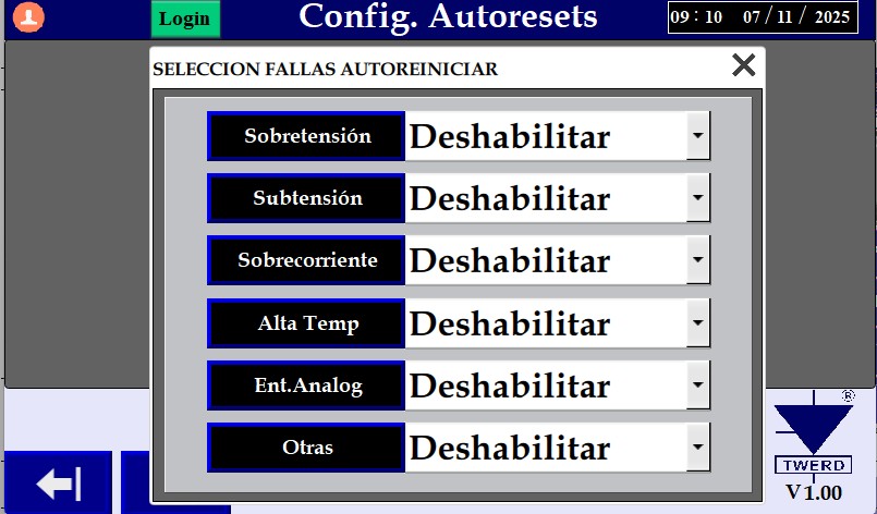
Operational functions | Number of attempts and restart times | Up to 6 user-programmable restarts, with timing adjustments via the "Total trial time" and "Delay time" parameters. Selection of faults to be reset using the automatic reset function. |
Programmable acceleration time | Programmable 0 to 600 seconds (internal VFD); programmable up to 6,000 seconds via HMI application. | |
Programmable deceleration time | Programmable internal VFD (0 to 600 seconds); programmable 0 to 6000 seconds via HMI application. | |
Starter type | Linear and S-type acceleration ramp. Acceleration ramp for programmable flakspin control independent of that used in normal operation. | |
Load torque type | Constant to Variable | |
Stop type | Linear and S-curve deceleration ramps; independently configurable ramp for emergency stops; programmable braking management function; DC injection braking (DC Hold function); flux braking. | |
Special Features | Internal PLC | Ability to control an external process without the need for an external PLC; 48 universal function blocks; 43 functions (including simple logic and arithmetic operations); an 8-state sequencer block; and 2 multiplexers with 8 inputs. |
Funciones Especiales | PID controller | Selection of reference signal source and feedback signal source, option to change error control signal polarity, Sleep function, output value limiting. |
Additional panel functions | Definition of user values for direct process observation, selection of unit of measurement, scale, and data source. LCD contrast adjustment. | |
Regulations | Product conformity | IEC/EN 50178:2003 IEC/EN 61800-5-1:2007 + IEC/EN 61800-3:2008 ISO9001 |