VFD Sine Wave Filter

Logo corporativo de Alnitech Power Solutions con isotipo de rayo cian
Logo HASSKE en color blanco, marca de filtros armónicos y senoidales para variadores de frecuencia

ALNITHOR AND HASSKE SINE WAVE FILTERS FOR VARIABLE FREQUENCY DRIVES

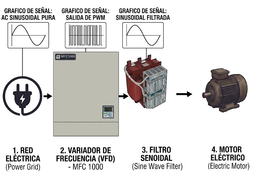
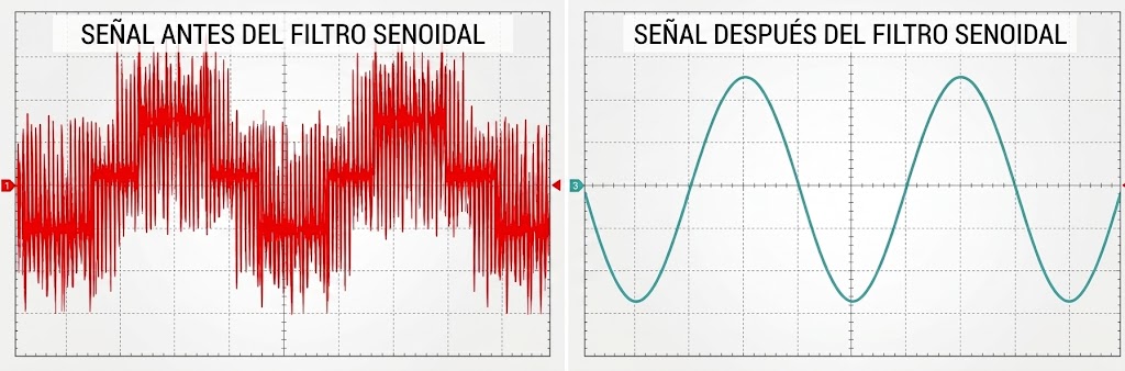
Output filter for variable frequency drives that converts the PWM waveform into a pure sine wave. Essential in artificial lift systems to eliminate overvoltages in the power cable and extend the service life of the electric submersible motor in oil and gas wells (ESP application).

Issue with PWM modulation and long cables between VFD and motor

When a variable frequency drive (VFD) powers an electric motor via a long cable run—typically exceeding 100 meters, such as in the common scenario of Electrical Submersible Pump (ESP) artificial lift wells reaching depths of thousands of feet—the quality of the delivered power severely degrades due to the physics of high-frequency electrical transmission. If a sine wave filter is not installed at the VFD output, the system is exposed to three critical phenomena:

1. High-Frequency PWM Pulse Generation (dV/dt)

Modern variable frequency drives (VFDs) utilize high-power, fast-switching transistors—primarily IGBTs—to generate an equivalent sinusoidal signal for the electric motor via Pulse Width Modulation (PWM).

While fast switching optimizes energy efficiency and reduces inverter switching losses, it introduces a significant physical challenge: the generation of rectangular pulses with extremely high rates of voltage change (dV/dt) and rise times of just 100 ns to 500 ns.

As this high-speed waveform travels along the power cable, the transmission line interacts with system impedances, transforming the signal as follows:

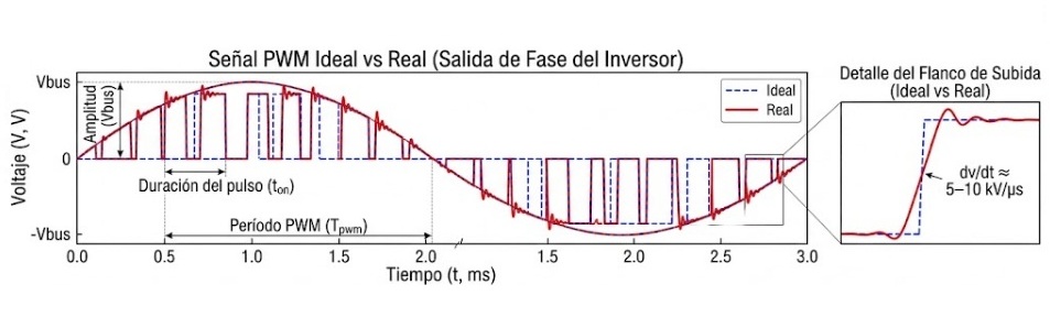
  • Behavior at the VFD Output (Nominal PWM Train): The inverter switches the DC bus voltage (Vbus), producing a burst of constant-amplitude pulses with widths that vary sinusoidally to reconstruct the motor current.
  • Transformation via the dV/dt Effect at Motor Terminals: The steep slope of the rising edge (dV/dt approx. 5–10 kV/µs) acts as an injection of very high-frequency components (in the MHz range).
Gráfica de señal PWM ideal vs real a la salida de fase del inversor con detalle del flanco de subida y velocidad de cambio dv/dt (5 a 10 kV/µs).

2. Reflected Wave Phenomenon

When the cable length between the VFD and the motor is substantial (approximately 100 meters, as in electric submersible pump (ESP) applications), the power cable and motor assembly ceases to behave as a simple conductor and begins to act as an electrical transmission line.

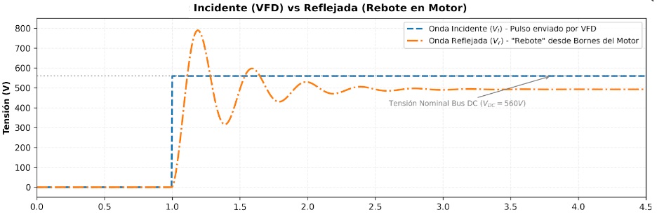
  • Impedance mismatch: Upon reaching the motor, the pulse energy encounters a “barrier” caused by the difference between the cable’s impedance and that of the stator winding.
  • The rebound effect: Since the motor cannot fully absorb it, a significant fraction of that energy rebounds (reflects) and travels back along the cable—or toward the surface, in the case of ESPs.
  • Wave collision: This reflected wave collides head-on with the new pulses that the drive continuously sends from the surface.
Gráfica de onda incidente del VFD vs onda reflejada por rebote de tensión en bornes del motor eléctrico.

3. Destructive Voltage Surges

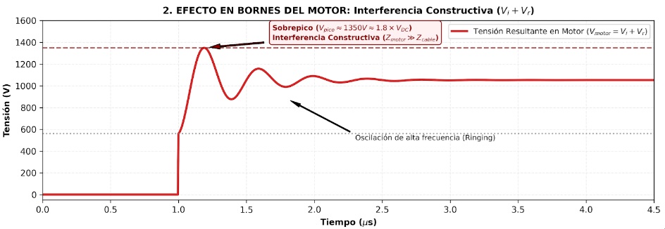
Upon reaching the motor, the incident and reflected waves add in phase (constructive interference).

This coupling instantaneously doubles the voltage amplitude, generating voltage spikes of up to twice the DC bus voltage (Vbus).

These destructive peaks progressively puncture the winding insulation and degrade the bearings via shaft currents, drastically reducing the motor’s service life.

Gráfica de interferencia constructiva y sobrepico de tensión por oscilación de alta frecuencia (ringing) en bornes del motor alimentado por VFD

Consequences of not using a sine wave filter at the VFD output

  • Voltage spikes due to reflected waves: Impedance mismatch between the power cable and the motor causes reflections that double the DC bus nominal voltage (peak voltage approx. 2 x VDC) at the downhole motor terminals.

  • Insulation puncture and degradation (Corona Effect): High voltage gradients (dv/dt) concentrate dielectric stress on the first turns of the stator winding, generating partial discharges that destroy the insulating varnish and cause short circuits.

  • Premature bearing damage (Shaft currents): Parasitic capacitances charge the rotor until the dielectric strength of the grease film in the bearings is exceeded, generating micro-electric arcs (pitting/fluting) that destroy the bearing raceways.

  • Motor overheating and thermal stress: High-frequency harmonic components of the PWM signal increase iron losses (due to eddy currents and hysteresis) and copper losses, raising operating temperatures and reducing energy efficiency.

  • Increased Electromagnetic Interference (EMI/RFI): High dv/dt slopes inject common-mode currents that travel through grounds and shielding, inducing electrical noise and interfering with downhole sensors, instrumentation, and communication buses.

  • Accelerated power cable aging: Submersible cable insulation undergoes constant dielectric fatigue due to transient spikes and heat generated by harmonic losses, increasing the likelihood of ground-fault insulation failures in the well.

  • High operating costs and unplanned downtime: The combination of these factors drastically reduces the system’s Mean Time Between Failures (MTBF), resulting in costly well interventions (pulling operations), premature equipment replacement, and deferred production losses.

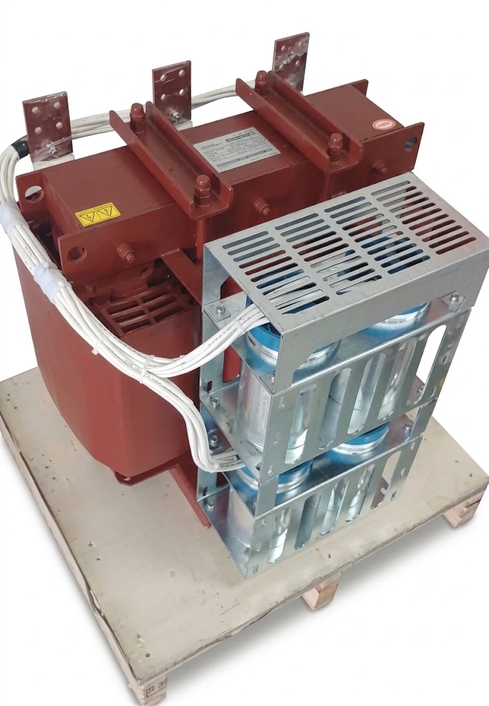
Filtro senoidal trifásico para variador de frecuencia VFD

Sine Wave Filter for Variable Frequency Drives in BES Artificial Lift Applications

The Challenge:

The rapid switching of IGBTs in the VFD generates dv/dt pulses that, as they travel along hundreds or thousands of meters of submersible cable, reflect and double in magnitude (2 x VDC) at the motor terminals, prematurely degrading the stator insulation.

Our Solution:

A high-efficiency power filtering system designed to operate between the VFD/transformer output and the wellhead, regenerating the voltage into a smooth, pure sine wave.


Key Benefits:

Benefits of Using Sine Wave Filters in BES Applications

  • Downhole Insulation Protection: Eliminates 2 x Vdc ​​bus transients at the submersible motor terminals, preventing dielectric failures in the windings and power cable splices (pigtail and penetrator).

  • Motor Heating Mitigation: Attenuates high-frequency harmonics and reduces iron and copper losses, keeping the ESP motor operating temperature within safe limits.

  • Compatibility with Long Cable Runs: Stabilizes the waveform across thousands of feet of power cable, reducing voltage distortion and ensuring clean power delivery to the pump.

  • Downtime Reduction: Minimizes well interventions (pulling) caused by electrical insulation failures, optimizing the artificial lift system’s Mean Time Between Failures (MTBF).

  • Rugged Design for Harsh Environments: Suitable for integration into containerized drives or electrical rooms at well pads and platforms, withstanding high ambient temperatures and continuous load variations.

Esta web utiliza cookies propias y de terceros para su correcto funcionamiento y para fines analíticos. Contiene enlaces a sitios web de terceros con políticas de privacidad ajenas que podrás aceptar o no cuando accedas a ellos. Al hacer clic en el botón Aceptar, acepta el uso de estas tecnologías y el procesamiento de tus datos para estos propósitos.
Privacidad